Combination Gas Valve Wiring Diagram
Vt Commodore Ignition Wiring Diagram, Complete Wiring Diagrams For Holden Commodore VT, VX, VY, VZ, VE, VF, 5.36 MB, 03:54, 32,796, John Amahle, 2018-08-01T19:37:41.000000Z, 19, Vt Commodore Ignition Wiring Diagram, to-ja-to-ty-to-my-to-nasz-swiat.blogspot.com, 1272 x 1800, jpeg, bcm pcm 12j swiat nasz, 20, vt-commodore-ignition-wiring-diagram, Anime Arts
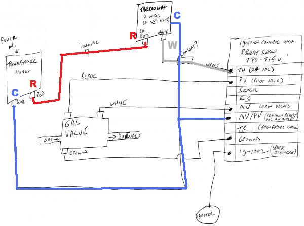
Natural to lp and lp to natural conversion kits available for standard and slow opening gas valves. All adjustments, wiring connections and pilot outlet are accessible from top of control. This is how to wire the thermopile to the 750mv gas valve for the pilot and main gas burners. This includes a wiring diagram.
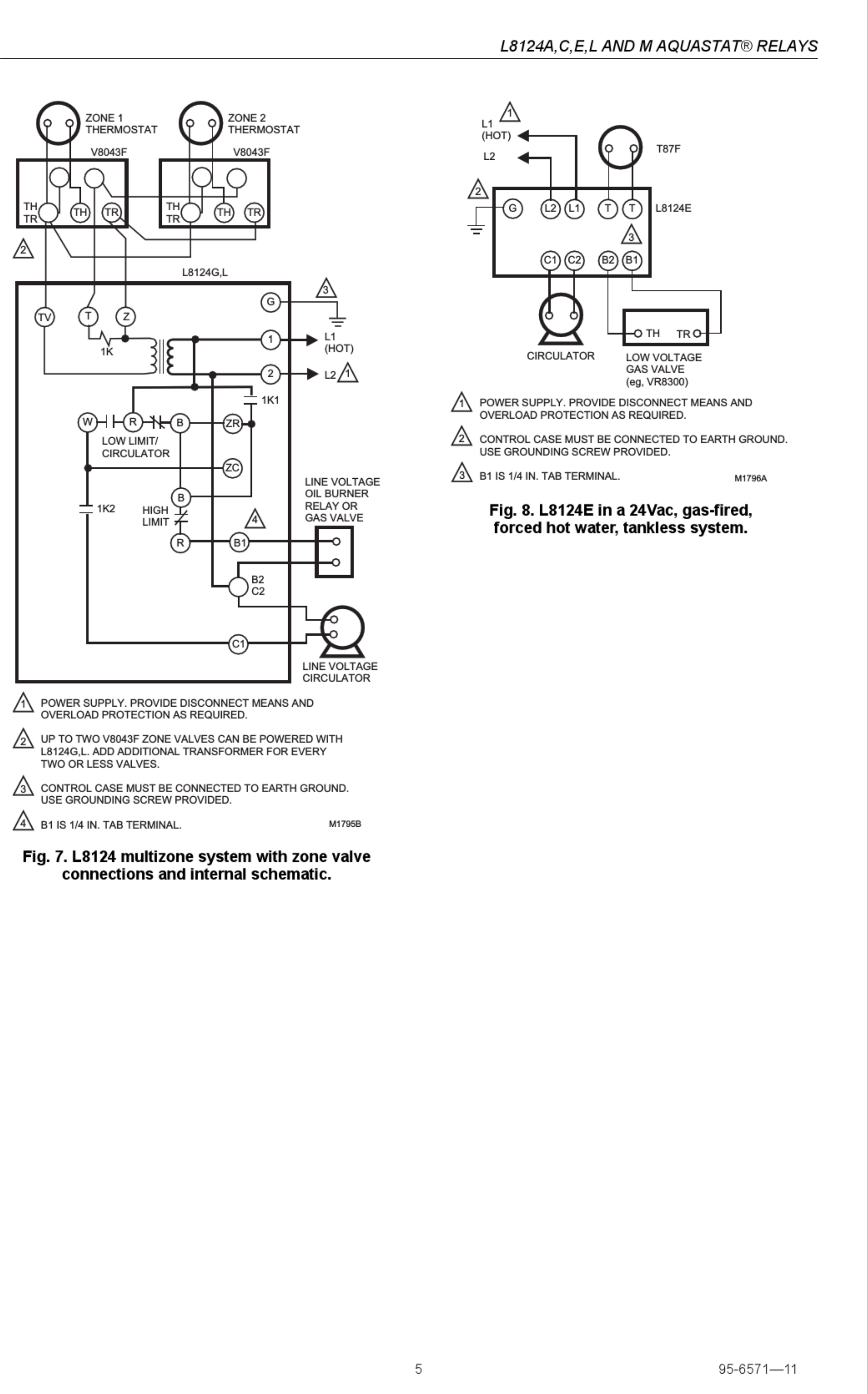
How to construct wiring diagrams controls fan limit control installation faqs sequence of operation for a gas fired furnace doug s hvac handy helper heil honeywell. The 36h series combination gas valve is designed with redundant and main solenoid valves that control gas flow to the main burners, a pressure regulator to maintain a constant outlet. Valve were combined into a single unit. (figure 2) the resulting combination valve was smaller and less costly. The body casting is that part of the combination gas control to which. A combination screw, 114 inch 0uick connect. The 857 model e midgitrol® combination gas valve. Provides all manual and automatic gas control. 700 & 710 millivolt wiring.
Honeywell Vr8200 Gas Valve Wiring Diagram
Honeywell Vr8200 Gas Valve Wiring Diagram
Honeywell Vr8200 Gas Valve Wiring Diagram

Honeywell Vr8200 Gas Valve Wiring Diagram

Honeywell Gas Valve Wiring Diagram - Atkinsjewelry

New brewstand - Gas Valve and Inbird wiring | HomeBrewTalk.com - Beer, Wine, Mead, & Cider

White Rodgers Gas Valve Wiring Diagram - General Wiring Diagram

Honeywell Vr8200 Gas Valve Wiring Diagram

Honeywell Millivolt Gas Valve Fireplace - Fireplace Ideas

Robertshaw Gas Valve Wiring Diagram
