5.3 Crankshaft Position Sensor Wiring Diagram
2 & 3 wire crank sensor wiring diagram (with pictures) the crankshaft position sensor is an electronic sensor that measures the position of the crankshaft. Scanning computer will not make a connection so i suspect a bad pcm.
Crank Sensor Wiring Diagram Wiring Diagram and Schematic
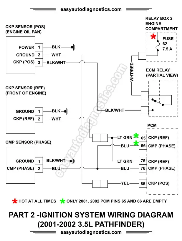
Ignition system circuit diagram 1996 1999 chevy gmc pick up and suv.
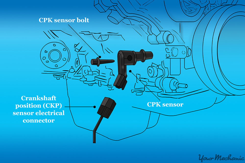
5.3 crankshaft position sensor wiring diagram. There are two most common types of crankshaft position sensors that are used commonly in the car. All gen iv 24x and 58x engines have a camshaft position sensor in the front timing cover. Where is a crank shaft sensor located at on a 94 chevy s10 b diy forums.
However the crank position sensor wiring isnt connected to anything. The following tutorial will help you to test the crankshaft position (ckp) sensor: Now in case you’re wondering what i mean by two and three wire types… i’m referring to;
Crankshaft position sensor wiring diagram. The chevy silverado utilizes a crankshaft position sensor in order to regulate the engine timing. This sensor uses a reluctor to gauge the position of the crank.
The illlustrations and info in this page apply only to 1996, 1997, 1998 dodge ram pickups, vans, and dakota with a 3.9l, 5.2l or 5.9l gasoline engine (that use the 3 connector pcm). Even if i bypass the relay and hardwire it on the engine still wont start. 5.3 crankshaft position sensor wiring diagram.
Od_7487] flow sensor wiring diagram as well bmw 325i crankshaft position sensor wiring diagram. Crankshaft position sensor replacement removal procedure. Today we have a chevy express we are replacing the crankshaft position sensor or ckp after removing the starter they are very easy to access the starter take.
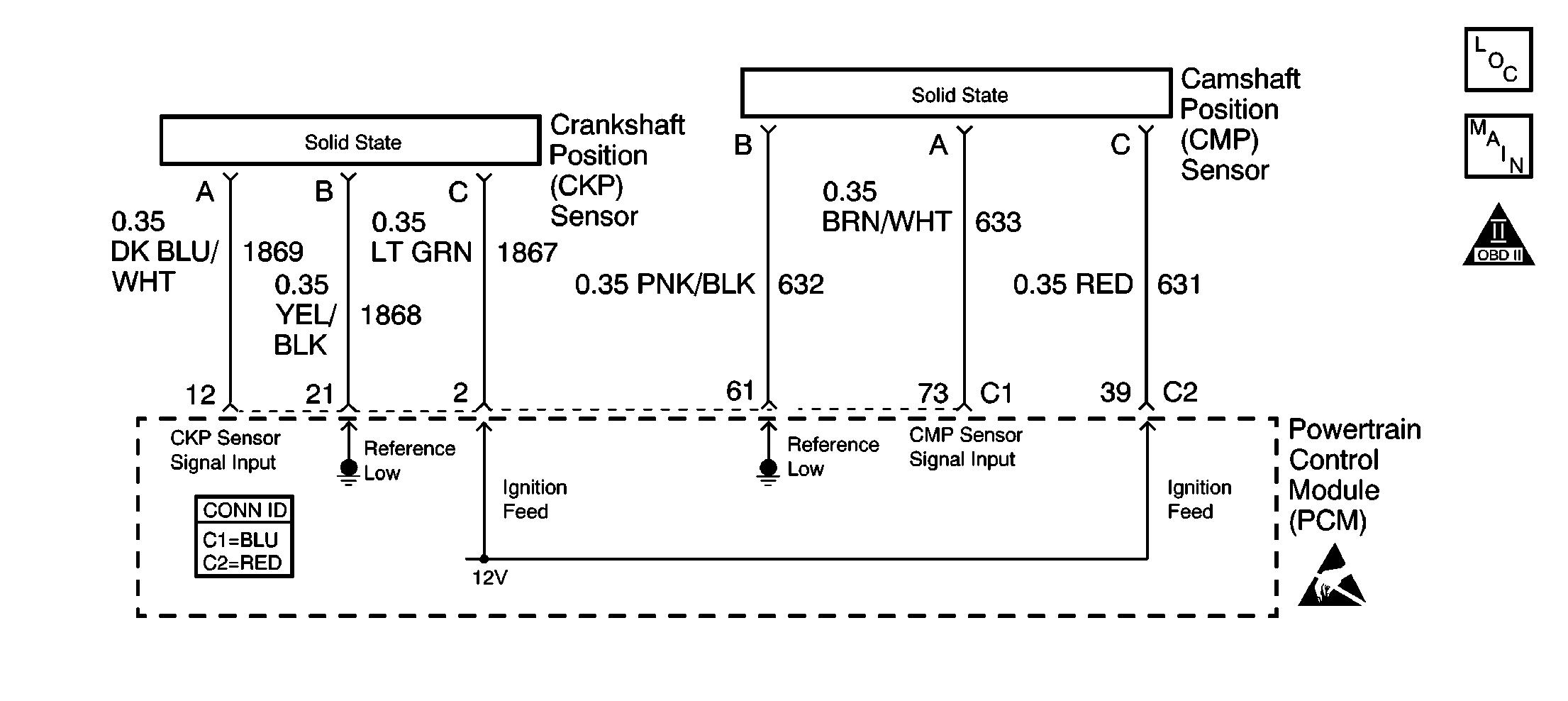
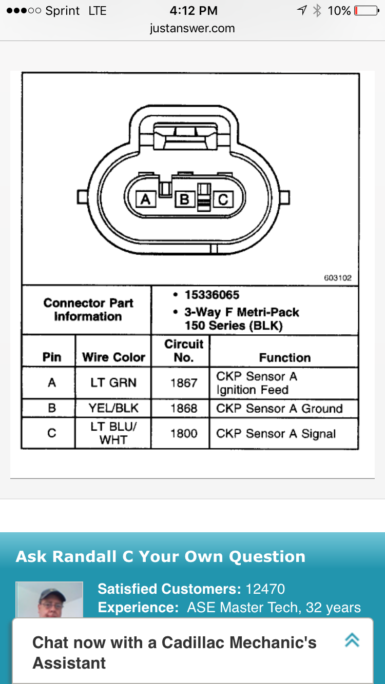
The ckp sensor has a b+ power supply, a ground, and a signal circuit. This sensor uses a reluctor to gauge the position of the crank. Schematics and diagrams gmc crankshaft position ckp sensor replacing.
It shows the components of the circuit as simplified shapes and the faculty and signal connections in the midst of the devices. Wiring diagram september 09 2020 0337. Im swapping in a 5.3 (2005) ive taken out the vats,but i still cant get it to start.
Crank sensor test (4.8l, 5.3l, 6.0l) no spark no start tests (at: Solved crank sensor coil pack computer wiring diagram fixya. The crankshaft position sensor works in conjunction with a 24x reluctor wheel mounted on the rear of the crankshaft.
2001 chevy silverado 1500 5 3 i need a wire diagram for the crank. Your harness may not have a pin in a location i have listed having a wire. After replacement of crankshaft position sensor, the computer needs to have the crankshaft position system variation learn procdeure performed.
Hooking this up for me these are fuseblock and pcm and other essential wiring diagrams schematron.org i need the schematic for a silverado c all the ones i have found so far come. In the absence of any problems, you can move on to finding hidden issues in the wiring diagram of the device. Diagram] crankshaft position sensor wiring diagram full version hd quality wiring diagram.
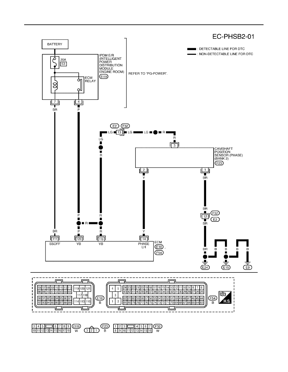
The gmc yukon utilizes a crankshaft position sensor in order to regulate the engine timing. 2001 tahoe 5.3 l p0343 camshaft position sensor circuit high input. These are the red & blue pcm connector pinouts that will cover 1999 to 2002 4.8/5.3/6.0.
2001 chevy silverado 1500 5 3 i need a wire diagram for the crank position sensors connector it was pulled off when. 99 silverado 5.3 pcm wiring diagram. When i turn it on the fuel pump primes but does not cut back on when i start cranking.
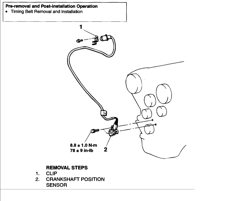
The amount of wires in their connector (of course there’s always an exception to every rule). This tutorial will help you test the ignition coil, ignition module, and the crankshaft position sensor: Disconnect the negative battery cable.raise and support the vehicle.
All gen iii engines have a camshaft position sensor in the rear of the engine behind the intake manifold. A wiring diagram makes it easier to check for shorts to ground or power and of course, check for continuity between the crank sensor. 1 wire harness installation instructions for installing harness numbers:
When the yukon’s ecm determines that there is an issue with the signal coming from this sensor, it’ll throw the p0335 trouble code. 5 3 wiring harness wiring diagrams here ls1tech camaro and firebird forum discussion diagram resistor wiring diagram crank sensor full version hd quality crank sensor meridiandiagram andreapendibene it part 2 crank sensor test no spark no start tests gm 4 8l 5 3l 6 0l diagram camshaft position sensor wiring diagram full version hd quality […] When the silverado’s ecm determines that there is an issue with the signal coming from this sensor, it’ll throw the p0335 trouble code.
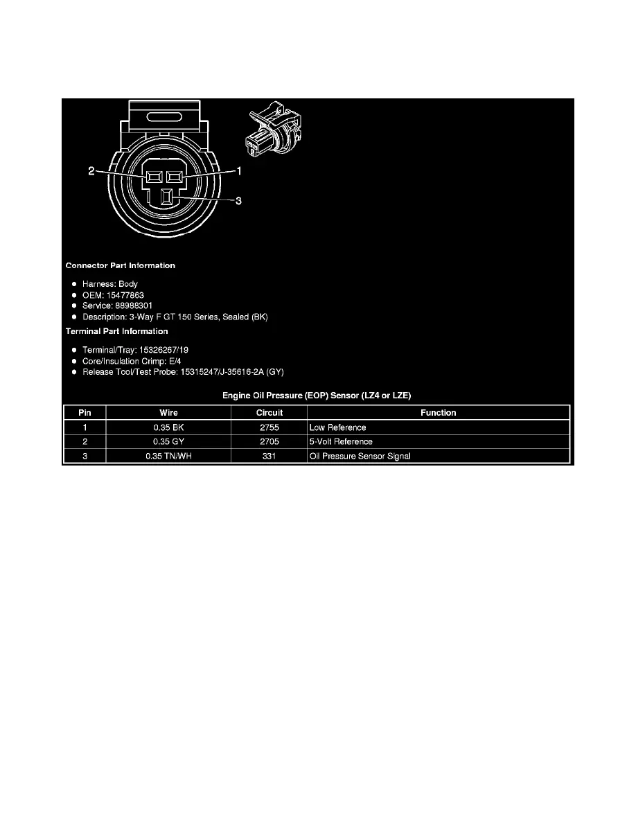
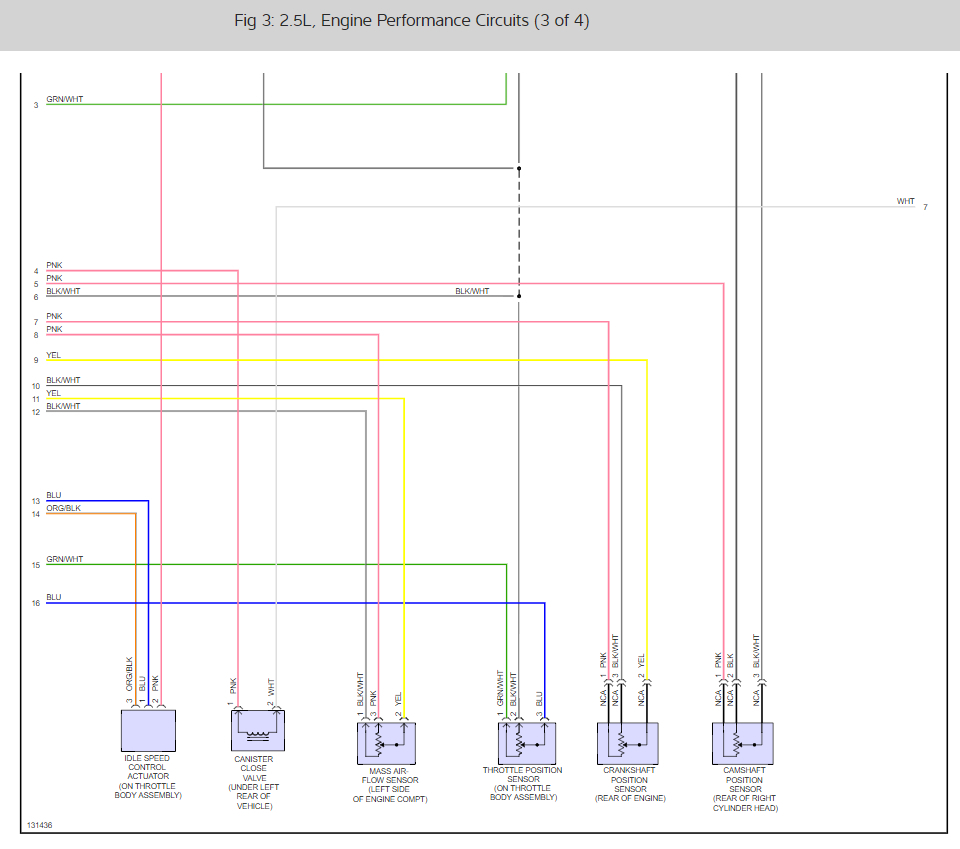
That requires a factory scan tool. Wire goes to which terminal re crank sensor wiring issues dec 24 2011 3 27am 3 wires on mine pink purple and yellow pink is 12v yellow is signal and purple is supposedly ground signal return pin a is 12v pin b is ground and pin c is signal, crankshaft position sensor wiring diagram you are welcome to our site this is images about crankshaft. Difference between vehicle speed sensor / engine speed sensor / crankshaft position.
Gen iv 24x engines use an e40 ecm and can be found in the 2005 corvette, 2005ñ2006 gto, 2005ñ2006 trailblazer, and 2005ñ 2006 ssr. To measure the spinning resistance of the crankshaft sensor use an ohmmeter (multimeter). Properly functioning sensor will range from 550 to 750 ohms.
Crankshaft sensor diagnosis with an ohmmeter. To measure the spinning resistance of the crankshaft sensor use an ohmmeter multimeter. I used the lt1swap.com diagrams to work the harness.
As the crankshaft rotates, the reluctor wheel teeth interrupt a magnetic field produced by a magnet within the sensor.

cmp sensor? LS1TECH Camaro and Firebird Forum Discussion
Crank Sensor Wiring Diagram Wiring Diagram and Schematic


Crankshaft Position Sensor Location Chevrolet Colorado
Chevy Malibu Engine Sensor Diagram
Wiring Diagram PDF 2002 Gmc Savana Van Wiring Diagram

Crank Sensor Wiring Diagram Wiring Diagram and Schematic
53 Crankshaft Position Sensor Wiring Diagram Crank by Design

Cam Sensor Wiring Diagram
Crank Sensor Wiring Diagram Wiring Diagram and Schematic

How To Install Replace Tps Throttle Position Sensor Vortec
What gives the crank sensor on a 2001 GMC Yukon with a 5

Wiring Diagram PDF 2002 Impala Camshaft Position Sensor
Cam Sensor Wiring Diagram
Ls1 crank sensor wiring question (please help) LS1TECH
Ls1 Crank Sensor Wiring Diagram Wiring Diagram
Crank Sensor Wiring Diagram Wiring Diagram and Schematic
2000 Jeep Cherokee Crankshaft Position Sensor Location

Wiring Manual PDF 01 Eclipse Camshaft Position Sensor

05 Silverado Crankshaft Alignment Sensor Wiring Diagram